What is an OTDR trace?
OTDR trace is a . sor, . trc, or other format file containing a graph with the data about the measured duct. Attenuation is a characteristic showing how much power (dB or dBm) is lost at a given location (attenuation at splice, cross) or in a given section of the duct.
How do you measure distance and loss in OTDR?
The OTDR measures distance to the event and loss at an event – a connector or splice – between the two markers. To measure splice loss, move the two markers close to the splice to be measured, having each about the same distance from the center of the splice.
What causes a ghost on an OTDR trace?
‘ Ghosts are false reflective events and can be difficult to distinguish because they are nonexistent events in the OTDR trace. The most common cause of ‘ghosts’ is an ‘echo’ of light reflected back and forth multiple times between strong real reflective events until it is attenuated to the noise level.
What is the acceptable dB loss for single mode fiber?
Type of fiber – Most single mode fibers have a loss factor of between 0.25 (@ 1550nm) and 0.35 (@ 1310nm) dB/km. Multimode fibers have a loss factor of about 2.5 (@ 850nm) and 0.8 (@ 1300nm) dB/km. The type of fiber used is very important.
How does a OTDR work?
OTDR injects a series of optical pulses into the fiber under test. It also extracts, from the same end of the fiber,light that is scattered or reflected back from points along the fiber. The strength of the return pulses is measured and integrated as a function of time, and is plotted as a function of fiber length.
What is the function of OTDR?
What is an OTDR? It is a fiber optic instrument used to characterize, troubleshoot and maintain optical telecommunication networks. OTDR testing is performed by transmitting and analyzing pulsed laser light traveling through an optical fiber.
How far maximum km can test with OTDR?
Assuming typical fiber attenuation of 0.20 dB/km at 1550 nm and splices every 2 km (loss of 0.1 dB per splice), a unit such as this one will be able to accurately certify distances of up to 120 km.
What is the dead zone in OTDR?
The OTDR dead zone refers to the distance (or time) where the OTDR cannot detect or precisely localize any event or artifact on the fiber link. It is always prominent at the very beginning of a trace or at any other high OTDR reflectance event.
What are the 2 basic event types on an OTDR trace?
OTDR Testing With Launch Cable In general, there are two types of dead zones—event dead zone (EDZ) and attenuation dead zone (ADZ). Event dead zone: the minimum distance between the beginning of one reflective event and the point where a consecutive reflective event can be detected.
What is purpose of OTDR?
An Optical Time Domain Reflectometer (OTDR) is a device that tests the integrity of a fiber cable and is used for the building, certifying, maintaining, and troubleshooting fiber optic systems.
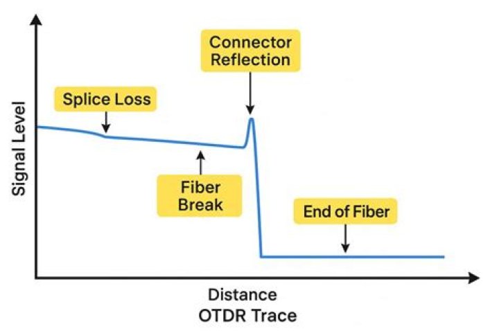
How do you read OTDR test results?
How to Read Your Trace. OTDR displays will show a Y and X axis. The X axis measures distance, and the Y axis measures attenuation and reflection in dB. Before running your trace, select the appropriate fiber network length, pulse width and acquisition time.
Which wavelength is recommended for OTDR testing?
Generally speaking, 1625 nm is the preferred wavelength for monitoring legacy 1310/1550-nm systems, largely due to laser cost. The 1650-nm wavelength is recommended for CWDM, DWDM, XGS-PON, and TWDM-PON systems where the traffic wavelengths extend into the L-Band.
