What is a JTAG header?
More often than not, the “JTAG connector” is a standard male header, such as a 0.1” header or a finer pitch header. As we have seen, there are only four (or five) pins required to operate a JTAG TAP. Most headers are shrouded or unshrouded male headers, with 10, 14, or 20 pins, and 0.1” or 0.05” pin pitch.
What is JTAG cable?
The JTAG-USB cable allows you to use your PC to connect to a JTAG scan chain or to access an SPI interface on a board equipped with the appropriate 6-pin header. In this way, you can program devices on Digilent programmable logic boards using the Digilent Adept Suite.
What are the different pins of JTAG cable?
Pinout
| JTAG connector | TI 14-Pin1 | ARM 10-Pin3 |
|---|---|---|
| Pin number | ||
| 4 | TDIS | SWDCLK / TCK |
| 5 | VTRef | GND |
| 6 | KEY | SWO / TDO |
What is ARM JTAG?
ARM JTAG 20. The ARM JTAG 20 connector is a 20-way 2.54mm pitch connector. It can be used in either standard JTAG (IEEE 1149.1) mode or Serial Wire Debug (SWD) mode.
Who uses JTAG?
JTAG has been in widespread use ever since it was included in the Intel 80486 processor in 1990 and codified as IEEE 1491 that same year. Today JTAG is used for debugging, programming and testing on virtually ALL embedded devices. With the invention of integrated circuits came the need to test physical interconnects.
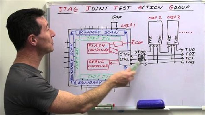
How does a JTAG work?
By providing a mechanism to control and monitor all the enabled signals on a device from a four-pin TAP, JTAG significantly reduces the physical access required to test a board. There are two main ways that this boundary scan capability can be used to test a board.
How many pins does JTAG use?
4
The official JTAG standard requires 4 standard pins (or signals), and defines an optional 5th. These signals, and the small bit of silicon logic that connects and controls them, are collectively referred to as the Test Access Port, or TAP controller.
What is the difference between JTAG and SWD?
SWD is an ARM specific protocol designed specifically for micro debugging. JTAG (Joint Test Action Group) was designed largely for chip and board testing. It is used for boundary scans, checking faults in chips/boards in production. Debugging and flashing micros was an evolution in its application over time.
What is serial wire debug?
Serial Wire Debug (SWD) is a two-wire protocol for accessing the ARM debug interface. It is part of. the ARM Debug Interface Specification v5 and is an alternative to JTAG.
